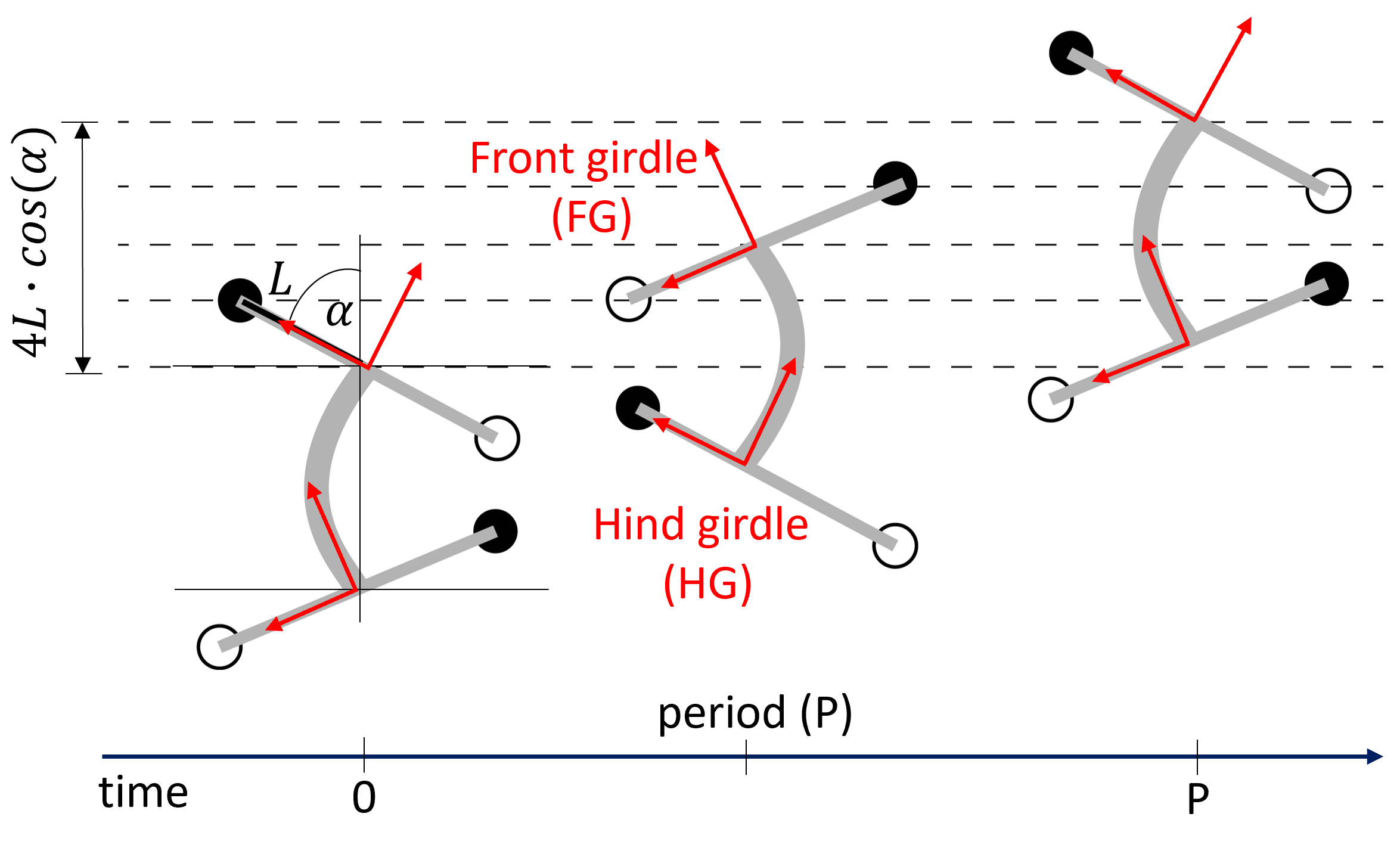
CoT is influenced by two factors for this study, which consist of energy consumption and the traveled distance. For traveled distance, we use a simple geometrical model to estimate the stride length of the robot (FIG_WEB1). In this model, we assume that stride lengths are constant without any slippage during locomotion, and the movements of the left and right legs are symmetrical. Therefore, we can calculate the stride length (![]() ) based on the assumption as follows:
) based on the assumption as follows:
Setting the front girdle frame as the body’s base (![]() ,
, ![]() ) allows us to calculate the position of the hind girdle frame (
) allows us to calculate the position of the hind girdle frame (![]() ,
, ![]() ) through the body’s forward kinematics (FIG_WEB2). This can be achieved by solving the following equation:
) through the body’s forward kinematics (FIG_WEB2). This can be achieved by solving the following equation:
where each segment length of our robot body is ![]() = 9 cm,
= 9 cm, ![]() = 7.5 cm,
= 7.5 cm, ![]() = 7.5 cm, and
= 7.5 cm, and ![]() = 9 cm. Each angle of rotation of body joints 1, 2, and 3 is defined as
= 9 cm. Each angle of rotation of body joints 1, 2, and 3 is defined as ![]() ,
, ![]() and
and ![]() , respectively. It is important to note that motor signals from the CPG-based neural controller drive the body joint angles.
, respectively. It is important to note that motor signals from the CPG-based neural controller drive the body joint angles.
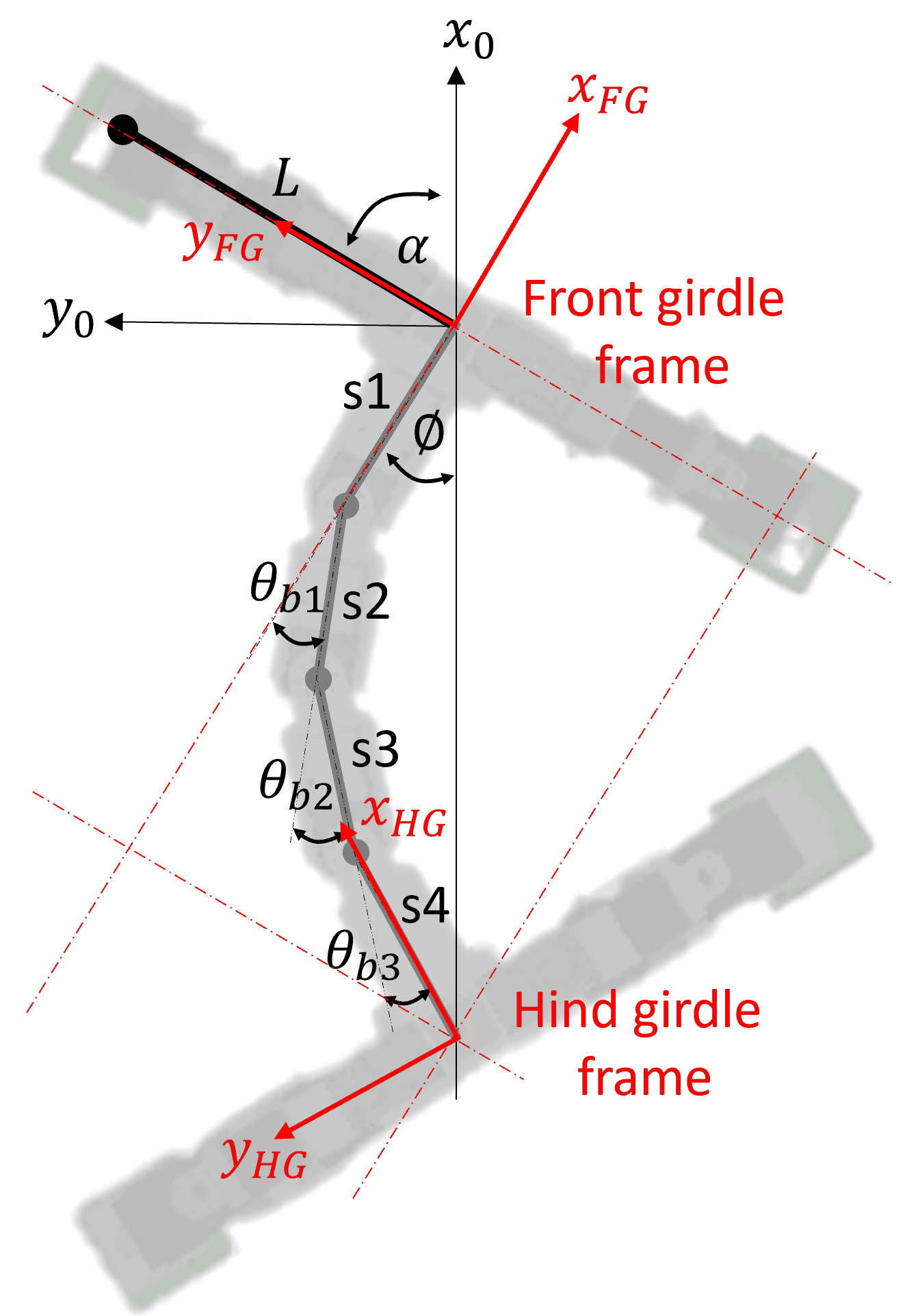
At the beginning of the stance phase, we assume that the forward direction of locomotion (i.e., x-axis of the world frame (![]() ) is aligned with the line passing through both girdles (see FIG_WEB2). Note that
) is aligned with the line passing through both girdles (see FIG_WEB2). Note that ![]() and
and ![]() represent the coordinates of the world frame. Therefore, we can calculate the angle of
represent the coordinates of the world frame. Therefore, we can calculate the angle of ![]() at the beginning of each stride as follows:
at the beginning of each stride as follows:
Where ![]() is the angle of the position of the hide girdle frame (
is the angle of the position of the hide girdle frame (![]() ,
, ![]() ) related to the front girdle frame (the body’s base frame). With the assumption that both girdles are aligned on the x-axis of the world frame (
) related to the front girdle frame (the body’s base frame). With the assumption that both girdles are aligned on the x-axis of the world frame (![]() ), this
), this ![]() can be interpreted as the angle between the x-axis of the world (
can be interpreted as the angle between the x-axis of the world (![]() ) and the body’s base frame or
) and the body’s base frame or ![]() (see FIG_WEB2).
(see FIG_WEB2).
Based on the geometric relationship of the model, we obtain the angle of ![]() for calculating the stride length (
for calculating the stride length (![]() ).
).
The body wave pattern is generated by using delay line units to shift the phase of the CPG signal (i.e., the output of CPG neuron 1 (![]() )) to obtain three different signals for driving three body joints. A delay line’s function is to add a time delay between its input and output, as shown by the equation below:
)) to obtain three different signals for driving three body joints. A delay line’s function is to add a time delay between its input and output, as shown by the equation below:
where ![]() the input signal (here the CPG signal).
the input signal (here the CPG signal). ![]() is the time step index (
is the time step index (![]() =0,1,2,…).
=0,1,2,…). ![]() is the delay factor.
is the delay factor. ![]() is the delayed output signal for motor control.
is the delayed output signal for motor control.
For our neural control network (Fig. 2A), there are three delay lines (![]() ,
,![]() ,
,![]() ) for driving three body joints (b1,b2,b3). All of them receive the same input signal, which is the output of CPG neuron 1 (
) for driving three body joints (b1,b2,b3). All of them receive the same input signal, which is the output of CPG neuron 1 (![]() ). We empirically adjusted the delay factors (
). We empirically adjusted the delay factors (![]() ,
,![]() ,
,![]() ) in the delay lines to determine the proper phase shifts of the output signals that control the body joints (b1,b2,b3), aiming to achieve body wave patterns or traveling waves.
) in the delay lines to determine the proper phase shifts of the output signals that control the body joints (b1,b2,b3), aiming to achieve body wave patterns or traveling waves.
For example, 50 %Trav (or 50% traveling wave) means that the phase of the second body joint b2 is shifted from the first body joint b1 by π/3 radians, and the phase of the third body joint b3 is shifted from b2 by π/12 radians or from b1 by π/3 + π/12= 5π/12 radians. To generate this body-wave pattern, we apply different delay factors to the CPG signal (![]() ) as follows:
) as follows:

where ![]() ,
, ![]() and
and ![]() are applied to control b1, b2, and b3, respectively.
are applied to control b1, b2, and b3, respectively. ![]() is set to zero (i.e., the output signal is the same as the CPG signal without any phase shifting).
is set to zero (i.e., the output signal is the same as the CPG signal without any phase shifting). ![]() is set to 20 to shift the phase of b2 from b1 by π/3 radians.
is set to 20 to shift the phase of b2 from b1 by π/3 radians. ![]() is set to 25 to shift the phase of b3 from b2 by π/12 radians or b1 by π/3 + π/12= 5π/12 radians. In our setup, the phase shift can vary from 0 to 2π by adjusting
is set to 25 to shift the phase of b3 from b2 by π/12 radians or b1 by π/3 + π/12= 5π/12 radians. In our setup, the phase shift can vary from 0 to 2π by adjusting ![]() from 0 to 120.
from 0 to 120.
According to the above mechanism, our control network with delay lines can generate various body wave patterns by setting the delay factors (![]() ).
).
The transition gradient of body movement is performed by simultaneously changing body patterns (%Trav) through the delay factors (![]() ,
,![]() ,
,![]() ) and stride frequency through the extrinsic modulatory input (MI) of the CPG model changing body patterns during the first three strides and subsequently maintaining the patterns after the third stride. The following rules are applied:
) and stride frequency through the extrinsic modulatory input (MI) of the CPG model changing body patterns during the first three strides and subsequently maintaining the patterns after the third stride. The following rules are applied:
(i) 1st stride: select a state with a minimum average of CoT.
(ii) 2nd and 3rd strides: change to a neighboring state in the minimum CoT region that exhibits the maximum velocity.
For more understanding, we used a state to represent body movement parameters which consist of percentage of traveling waves (%Trav) and stride frequency when the robot climbs at different slope angles. For example, ![]() indicates that the robot climbs at 30 degrees and during the 1st stride the robot performs 16% of traveling waves (
indicates that the robot climbs at 30 degrees and during the 1st stride the robot performs 16% of traveling waves (![]() =0,
=0, ![]() =6,
=6, ![]() =8) with a stride frequency of 0.33 Hz (MI=0.18).
=8) with a stride frequency of 0.33 Hz (MI=0.18).
More specifically, we demonstrated a body-wave transition strategy at a 30-degree slope angle from the first to third stride step-by-step (Fig. 3B):
1st stride: the robot begins climbing at 30 degrees with a %Trav of 16% and stride frequency of 0.33Hz. At the moment, the speed of the robot is 0.048 m/s and CoT is lowest value (0.28). The blue circle indicates the selected state ![]() , and the blue transparent arrow represent the state transition.
, and the blue transparent arrow represent the state transition.
2nd stride: the robot performs the next state ![]() . By performing the first two strides, the robot consumes 0.20 of CoT and its speed is 0.066 m/s.
. By performing the first two strides, the robot consumes 0.20 of CoT and its speed is 0.066 m/s.
3rd stride: the robot proceeds to the steady state ![]() . By performing the first three strides, the robot speed is 0.085 m/s and CoT = 0.16.
. By performing the first three strides, the robot speed is 0.085 m/s and CoT = 0.16.
Therefore, the gradient transition for climbing at 30 degrees can be generated as a series of state: ![]() ,
, ![]() , and
, and ![]() from the first, second and third strides, respectively. Furthermore, the gradient transition strategy of a 30-degree slope angle is applied to a real robot with its body joint signals illustrated in Fig. 5C.
from the first, second and third strides, respectively. Furthermore, the gradient transition strategy of a 30-degree slope angle is applied to a real robot with its body joint signals illustrated in Fig. 5C.